The magnetic flowmeter is a meter for measuring conductive liquids according to Faraday's law of electromagnetic induction. The electromagnetic flowmeter consists of three parts: sensor, converter and cable connection. If the cable connection is short, install it in the flowmeter housing.
The electromagnetic flowmeter has a series of excellent characteristics that can solve the problems that other flowmeters are not easy to apply, such as the measurement of dirty flow and corrosion flow.
advantage:
The measuring channel is a smooth straight pipe with no obstruction. It is suitable for measuring liquid-solid two-phase fluids containing solid particles, such as pulp, mud, sewage, etc.
The pressure loss caused by the flow detection is not generated, and the energy saving effect is good;
The measured volumetric flow is virtually unaffected by changes in fluid density, viscosity, temperature, pressure, and conductivity;
Large flow range and wide range of caliber;
Corrosive fluids can be applied.
Disadvantages:
Can not measure liquids with very low conductivity, such as petroleum products;
Cannot measure gases, vapors, and liquids containing large bubbles;
Cannot be used for higher temperatures. 
Commonly used electromagnetic flowmeters in chemical plants are joint ventures or imported brands such as E+H (Endershaus), KROHNE (Cologne), ABB, Yokogawa, Siemens, etc. The domestic electromagnetic flowmeter brands include Shanghai Guanghua, Sichuan Instrument, Weil Tai, Xisen, Zhejiang Diyuan and so on.
Installation requirements for electromagnetic flowmeters
Installation site selection
In order to make the electromagnetic flowmeter work stably and reliably, the following aspects should be noted when selecting the installation location:
1. Try to avoid ferromagnetic objects and equipment with strong electromagnetic fields (large motors, large transformers, etc.) to prevent the magnetic field from affecting the working magnetic field and flow signal of the sensor.
2. It should be installed in a dry and ventilated place to avoid sun and rain. The ambient temperature should be -20~+60°C and the relative humidity should be less than 85%.
3. There should be plenty of space around the flowmeter for easy installation and maintenance.
Eleven installation suggestions
1. Ensure full pipe installation
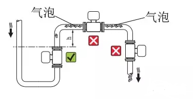
The electromagnetic flowmeter measuring tube must be in a full tube state, and the non-full tube state cannot occur. If the pipe is not full or the outlet is vented, the sensor should be mounted on a siphon.
Avoid installing upstream of the down pipe 
 2. Horizontal and vertical installation
 The sensor can be mounted horizontally and vertically, but it should be ensured that the effects of deposits and bubbles on the measuring electrode are avoided and the axial direction of the electrode is kept good. When mounted on a horizontal pipe, the two measuring electrodes should not be directly above and below the pipe. When installed vertically, the fluid should flow from bottom to top.
The inlet straight pipe section should be larger than 5D, and the outlet straight pipe section should be larger than 2D. If there are specific installation requirements, it should be installed according to the instructions of the electromagnetic flowmeter. The plug-in inlet straight pipe section should be ≥ 20 D and the outlet straight pipe section ≥ 7D (D is the nominal diameter of the sensor. 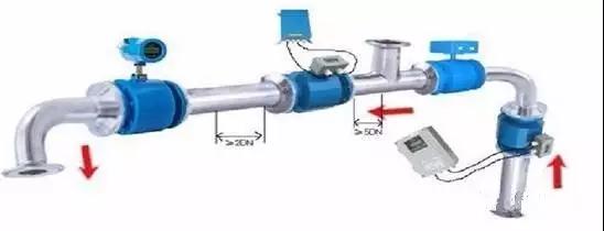
When the outlet is vented, the sensor should not be installed where the pipe is vented and should be installed at a lower location. When the sensor is installed under the pipe, the sensor should be filled with liquid and the empty pipe state should not occur.
4 series installation and parallel installation
If there are several sensors that need to be connected in series on the same pipe in sequence, the distance between each sensor should be at least 2 sensors.
If more than two sensors are installed in parallel with each other, the distance of the sensor must be greater than 1 m.
5 installation between elbow, valve and pump
In order to ensure the stability of the measurement, a straight pipe section should be provided before and after the sensor, and the length is given by the following figure. If this is not possible, a stabilizer should be used or the cross-sectional area of ​​the measuring point should be reduced. 
Installation plus bypass pipe
In the pipeline where the flowmeter is installed, there should be a valve that can cut off the medium in the pipeline to facilitate daily maintenance and maintenance. The process does not allow flow to be interrupted. A bypass line can be added to the pipe on which the flow meter is installed.
7. Install in the direction of calibration
When the flowmeter sensor has a clear flow indication, it should be installed in the calibration direction.
8 inlet, cable and threading tube
The flow meter inlet, cable and threading tube should be bent downwards and open at the lowest point to avoid water ingress and short circuit.
9. Welding flange
When installing the flowmeter, the flange should be welded first, then the flowmeter should be installed. The flange of the flowmeter sensor should not be directly welded to prevent the slag from burning out the lining.
10. Distance between converter and sensor
The signal line between the converter and the sensor must not exceed 50m, and the signal line must be sheathed with a galvanized tube.
11. Sensor grounding measures
The flow signal generated by the sensor is very small and only a few millivolts at full scale, so the sensor ground should be good. There are two aspects to the grounding requirements of an electromagnetic flowmeter:
From the working principle of the electromagnetic flowmeter and the loop of the flow sensing signal current, the ground of the sensor and the converter must be at the same potential as the measured medium.
Grounding, with zero potential on the earth, reduces external interference.
Under normal circumstances, the process pipes are all metal pipes, which are all grounded, which is easy to meet. However, in the case of large external electromagnetic field interference, the electromagnetic flowmeter should be separately provided with a grounding device. The grounding wire should be a multi-strand copper wire with a cross-section larger than 5mm2. The grounding wire of the sensor must not be connected to the common ground of the motor or other equipment. To avoid the effects of leakage current. The grounding resistance should be less than 10Ω.
Electromagnetic flowmeter failure and troubleshooting
Acceptance of electromagnetic flowmeter
In the acceptance phase, the sensors, converters and connecting cables are generally tested.
For the sensor, it can be measured according to the empty tube:
Electrode insulation performance;
Excitation coil resistance and insulation performance;
Check the goodness of the lining material;
For converter detection, the analog signal generator should be used. It is forbidden to connect the converter to the sensor and check the converter output. Because it is an empty tube, the output information and display information are random.
For connection cable inspection, mainly check whether the cable type and length meet the requirements.
Initial assembly and debugging of electromagnetic flowmeter
Should focus on the following analysis and inspection:
Whether the working condition of the meter meets the requirements (humidity, pressure, flow rate, protection level);
Whether the instrument selection is correct;
Whether the instrument installation is reasonable (grounding, front and rear straight pipe sections, wiring)
Gathering point - should avoid bubble accumulation
Non-full tube - to ensure full tube status during measurement
Siphon mouth - can not produce siphon
Front valve - the regulating valve should be installed downstream of the flow meter
Rear pump - upstream pump to remove negative pressure
It should also consider the external interference introduced by the connecting cable, and the failure of the meter itself is not excluded;
After the power is turned on, the zero point must be adjusted while the electromagnetic flow sensor is full of liquid.
Inspection work after electromagnetic flowmeter operation
Zero check for regular stop flow for use conditions:
Sensor electrodes wear, corrode, leak, and scale. Especially for precipitated, easily contaminated electrodes, non-cleaning liquids containing a solid phase;
The excitation coil insulation is lowered;
The converter insulation drops;
Converter circuit failure;
The connecting cable is damaged, short-circuited, or damp;
New changes in instrument usage conditions are not excluded.
Common faults and troubleshooting methods in Q&A electromagnetic flowmeter operation
1. There is no signal output from the instrument flow?
Cause Analysis:
The meter is not powered properly;
The cable connection is not normal;
Liquid flow conditions do not meet installation requirements;
Damage to the sensor components or measurement of the inner wall with an adhesive layer;
The converter component is damaged.
solution:
Confirm that the power is connected, check whether the voltage of each output of the power circuit board is normal, or try to replace the entire power circuit board to judge whether it is good or bad.
Check that the cable is intact and that the connection is correct.
Check the direction of liquid flow and the filling of the liquid in the tube. For electromagnetic flowmeters that can measure forward and reverse, if the direction is inconsistent, it can be measured, but the set display flow does not match the positive and negative directions, and must be corrected. If the sensor is large, the direction of the arrow on the sensor can be changed and reset. The meter symbol is displayed. If the pipeline is not filled with liquid, it is also caused by improper installation of the sensor. Measures should be taken during installation to avoid causing the liquid in the pipeline to be unsatisfactory.
Check that the electrode on the inner wall of the transmission is covered with a liquid crust layer. For the measurement liquid that is easy to scab, it should be cleaned regularly.
2. The output value fluctuates?
Cause Analysis:
Most of these failures are caused by the measurement medium or the external environment. After the external interference is removed, the fault can be eliminated by itself. In order to ensure the accuracy of the measurement, such failures can not be ignored. In some environments, due to the large vibration of the measuring pipe or liquid, the circuit board of the meter may be loosened, which may also cause fluctuations in the output value.
solution:
Confirm whether the flow is actually caused by the process operation. At this time, the flowmeter only reflects the flow condition as it is, and the fault can be eliminated by itself after the pulsation is over.
Electromagnetic interference caused by external stray currents, etc. Check whether the instrument operating environment has large electrical appliances or welding machines at work. Make sure that the instrument is grounded and the operating environment is good.
When the pipe is not filled with liquid or the bubble contains bubbles, both are caused by process reasons. At this point, the technician can be requested to confirm that the output value can be restored after the liquid is filled or the bubble is flattened.
The transmitter circuit board is a plug-in structure. Due to the large vibration of the pipeline or liquid in the field, the power supply board of the flowmeter is often loosened. If loose, remove the flowmeter and re-fix the board.
3. Is there a signal output when there is no flow after power-on?
Cause Analysis:
Input shielding or poor grounding, introducing electromagnetic interference;
The instrument is close to a strong electric device or a high frequency pulse interference source;
The pipeline has strong vibration;
Converter agility is too high;
Approach:
Improve shielding and grounding and eliminate electromagnetic interference;
Eliminate the installation of interference sources and take isolation measures to enhance power supply filtering;
Take shock absorption measures and strengthen signal filtering to reduce amplifier agility;
Reduce agility and improve trigger levels.
4
Is the measurement error large?
Cause Analysis:
In-tube pressure is too high
Engineering pressure selection is wrong;
Damage to the seal;
The sensor is eroded;
Approach:
Adjust the high pressure and change the installation position;
Use high-grade engineering pressure sensor;
Replace the seal;
Take anti-corrosion and protection measures.
If it is determined that the fault is caused by damage to the converter element, replace the damaged component.
ChemSta has been dedicated in designing and manufacturing devices used in oil production lines and vegetable protein production lines for more than 30 years. Up to now, there are about 200 successful engineering cases at home and abroad. We have hired over 100 professional engineers in various fields such as machinery, food, electricity and architecture. Hence, we are able to provide appropriate system solutions to meet customer`s requirements.
Vegetable Oils Machine,Vegetable Oils Equipment,Vegetable Oils Machinery,Vegetable Oils Production Line
Shandong ChemSta Machinery Manufacturing Co.,Ltd. , https://www.oil-proteinmachine.com